


Sistema de agua helada
Sistema de agua helada
A Sistema de agua helada is an HVAC system using low-temperature water for cooling and dehumidification, common in large buildings like skyscrapers, malls, and hospitals.
Chilled water systems represent a significant type of air conditioning technology, employed widely in large-scale buildings such as the Burj Khalifa and Merdeka 118. Due to their complexity and prevalence in structures like hotels, offices, shopping malls, and hospitals, understanding their operation is crucial for efficient building management. Surveys indicate that space cooling can account for a substantial portion of a commercial building's energy consumption (e.g., studies suggest around 42% in some regions). A thorough understanding allows engineers, technicians, maintenance personnel, and building managers to optimize performance and potentially achieve significant energy savings.
This article details the major components, key design considerations, and common system diagrams associated with chilled water systems.
Definition
A Sistema de agua helada is an air conditioning system that utilizes chilled water (low-temperature water, typically between 6-12°C or 42-54°F) circulated through pipes to cool and dehumidify air within a building. It comprises multiple interconnected components performing functions such as water cooling (refrigeration), water circulation (pumping), air cooling and dehumidification (air handling), and heat rejection.
Unlike direct expansion (DX) systems that use refrigerant directly in air handling coils, chilled water systems use water as a secondary cooling medium. Air Handling Units (AHUs) or Fan Coil Units (FCUs) located throughout the building circulate air across coils containing chilled water, thereby cooling and dehumidifying the space. The efficiency and consistency of the system depend heavily on the selection and integration of its components.
Components
Understanding the individual components and their various types is essential, as these choices significantly impact system performance, efficiency, and suitability for specific applications. The major components include:
-
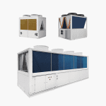
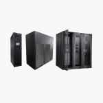
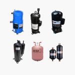
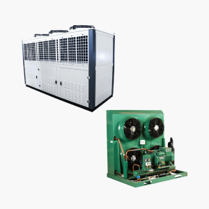
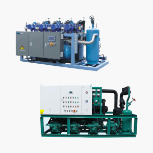
Chiller
The Chiller is the core component, responsible for producing chilled water. It operates based on the refrigeration cycle (compression, condensation, expansion, evaporation) to remove heat from the water loop that circulates to the building's air handlers. Chillers are typically the largest energy consumers in the system.
Using water as a heat transfer medium is advantageous due to its high specific heat capacity (approx. 4.2 kJ/kg·K compared to air's 1.005 kJ/kg·K) and availability. Centralizing the refrigeration process in one or more large chillers avoids the need for numerous individual compressors throughout a large building, simplifying maintenance and potentially improving overall efficiency and reliability.
Heat absorbed by the chiller from the building must be rejected to the environment. This leads to different chiller classifications based on the heat rejection method.
-
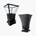
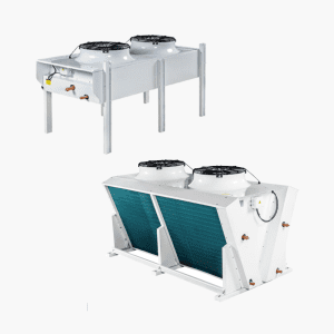
Heat Rejection Equipment (e.g., Cooling Tower)
Chillers reject the absorbed heat either directly to the ambient air (air-cooled) or via a separate water loop to a heat rejection device (water-cooled).
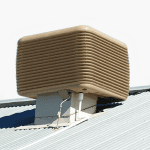
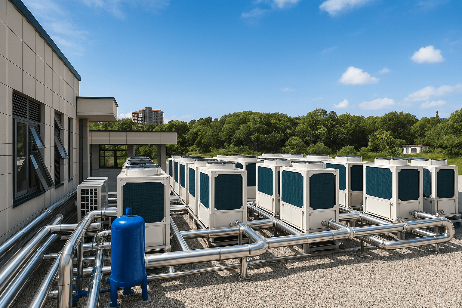
Torres de enfriamiento are commonly used with water-cooled chillers. They facilitate heat rejection from the condenser water loop to the atmosphere, primarily through evaporation. Water from the chiller's condenser (condenser water) is pumped to the cooling tower, distributed over a fill medium to maximize air-water contact, and cooled as ambient air is drawn through the tower, causing some water to evaporate. The cooled condenser water then returns to the chiller.
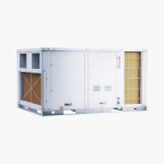
Air-Cooled Chillers utilize fans to force ambient air directly over their condenser coils, rejecting heat without the need for a cooling tower and condenser water loop. This simplifies the system but often results in lower energy efficiency compared to water-cooled systems, especially in hot climates.
-
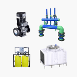
Pumps
Pumps are required to circulate water through the different loops of the system:
- Chilled Water Pumps: Circulate chilled water between the chiller(s) and the AHUs/FCUs.
- Condenser Water Pumps: Circulate condenser water between the water-cooled chiller(s) and the cooling tower(s).
Pump arrangement and control strategy (e.g., constant vs. variable speed) significantly affect system efficiency and stability.
-
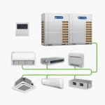
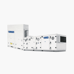
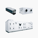
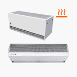
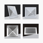
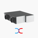
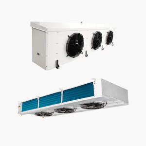
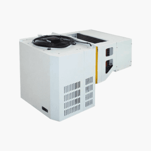
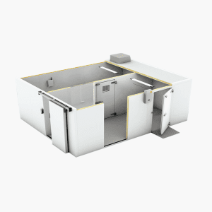
Air Handling Unit (AHU) / Fan Coil Unit (FCU)
AHUs and FCUs are terminal units responsible for conditioning the air within occupied spaces. They typically consist of a fan, cooling coil (through which chilled water flows), filters, and sometimes heating coils, humidifiers, or energy recovery devices. Air is drawn from the space (or outdoors), passed over the cooling coil where it transfers heat to the chilled water, and then supplied back to the space at a lower temperature and humidity. AHUs generally serve larger zones or multiple rooms, while FCUs are typically smaller and serve individual rooms.
-
Ancillary Components
Several other components are essential for proper operation:
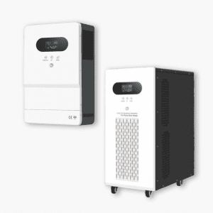
- Expansion Tank: Accommodates changes in water volume due to temperature fluctuations in the closed chilled water loop and helps maintain system pressure.
- Makeup Water System: Replenishes water lost due to evaporation in cooling towers or leaks in the system.
- Water Treatment System: Maintains water quality in both chilled and condenser water loops to prevent corrosion, scaling, and biological growth, ensuring efficiency and longevity.
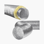
- Piping: Interconnects all components for water distribution.
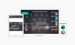
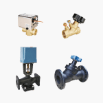
- Valves & Controls: Regulate water flow, temperature, and pressure throughout the system for efficient operation and zone control.
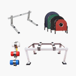
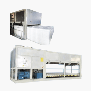
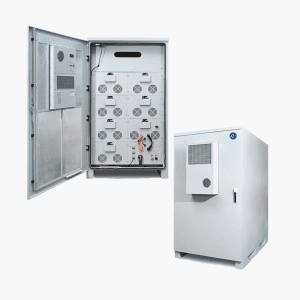
- Thermal Energy Storage (TES) Tanks: Used in some systems (especially district cooling) to store chilled water generated during off-peak hours for use during peak demand, reducing operating costs.
System Design Considerations
Designing an efficient and effective chilled water system involves several key decisions:
-
Operating Temperatures
Determining the supply and return chilled water temperatures (and thus the temperature difference, or Delta T) is fundamental. Common designs might use a supply temperature of 6.7°C (44°F) and a return of 12.2°C (54°F), resulting in a Delta T of 5.5°C (10°F). However, designing for a higher Delta T (e.g., 8.3°C or 15°F) can reduce required water flow rates for the same cooling load, potentially saving pump energy, though it may impact chiller efficiency and dehumidification capacity.
-
Chiller Type Selection
The choice depends on factors like efficiency requirements, available space, climate, initial cost, maintenance considerations, and availability of heat recovery opportunities.
Based on Heat Rejection:
- Water-Cooled: Generally more energy-efficient, especially for large capacities, but require cooling towers and a condenser water loop.
- Air-Cooled: Simpler installation (no cooling tower), potentially lower initial cost, but often less efficient and can be noisy.
- Evaporative Condensing / Hybrid: Combine air-cooling with water spray over the condenser coil for improved efficiency over standard air-cooled units.
Based on Compressor Technology:
- Centrifugal: Efficient for large loads, often use low-pressure refrigerants, may have limited turndown (part-load efficiency). Oil-free magnetic bearing options available.
- Screw (Single or Twin): Good part-load efficiency, wider operating range than centrifugals, suitable for medium to large loads.
- Scroll: Common in smaller chillers, reliable, good efficiency, often used in modular chiller arrangements.
- Reciprocating: Older technology, less common now due to lower efficiency compared to others.
Other Types:
- Absorption Chillers: Use a heat source (like waste heat, steam, or natural gas) instead of mechanical compression, beneficial where cheap heat is available or electricity costs are high.
- Heat Recovery Chillers: Designed to capture condenser heat for useful purposes like domestic hot water or space heating.
-
Number and Sizing of Chillers
Instead of a single large chiller, multiple smaller chillers are often used to provide redundancy (system can still operate if one chiller fails) and improve part-load efficiency (operating fewer chillers near their optimal efficiency point). A common strategy involves using identically sized chillers, or sometimes incorporating a smaller "pony" chiller to handle low-load conditions efficiently (e.g., overnight).
Chillers have a minimum operating capacity (turndown limit, e.g., 20-30% of full load). The plant must be designed to meet the building's minimum load without causing chillers to cycle excessively or trip. Using multiple units allows for better matching of plant capacity to the actual cooling demand.
-
Pumping Arrangement (System Configuration)
The way pumps are configured affects flow stability, control, and energy consumption.
- Primary-Secondary Flow: Uses two sets of pumps in the chilled water loop. Primary pumps maintain constant flow through the chillers, ensuring stable operation. Secondary pumps use variable speed drives (VSDs) to vary flow to the building based on demand. This decouples chiller flow from building flow, providing stability but potentially adding complexity and cost.
- Variable Primary Flow (VPF): Uses a single set of variable speed pumps for the entire chilled water loop. This can be more energy-efficient and have lower initial cost (fewer pumps) but requires careful design and control to ensure minimum required flow through the active chiller(s) at all times.
-
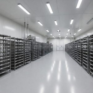
Load Profile and Zoning
Understanding the building's cooling load profile (how demand varies daily and seasonally) is crucial. Different areas may have different needs (e.g., offices vs. server rooms). Areas with continuous cooling needs (like data centers) might require dedicated systems (potentially DX) or special consideration within the central plant design, as operating a large central system for a very small load is inefficient.
Chilled Water System Diagrams
Various diagrams are used to represent chilled water systems, illustrating different levels of detail and aspects of the design:
- Overall System Schematic: Shows the main components (chillers, cooling towers, pumps, representative AHUs/FCUs) and their interconnections via piping loops (chilled water, condenser water). Indicates quantities, major equipment types, and basic control concepts. (Example: A plant with multiple water-cooled centrifugal chillers).
- District Cooling Plant Diagram: Depicts a large central plant serving multiple buildings. May include features like thermal energy storage (TES) tanks, primary/secondary distribution loops, and heat exchangers at building interfaces. Focuses on the central plant and primary distribution.
- Network Piping Diagram: Shows the layout of distribution piping from the central plant to and within the buildings served, particularly relevant for district cooling or large campus systems. May illustrate routing, pipe sizes, and connections to building interfaces or main risers.
- Building Riser Diagram: For high-rise buildings, this diagram shows the vertical distribution of chilled water piping connecting the plant (often in the basement or on the roof) to AHUs/FCUs on different floors. Illustrates zoning and connection sequencing.
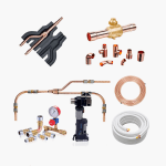
- Detailed Equipment Connection Diagram: Provides specifics for connecting individual components like chillers or pumps, showing isolation valves, control valves, strainers, gauges, sensors, bypass lines, and exact pipe configurations necessary for installation and maintenance.