


Variable Refrigerant Flow (VRF) Systems: A Technical Overview
Variable Refrigerant Flow (VRF) System
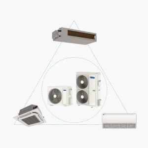
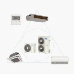
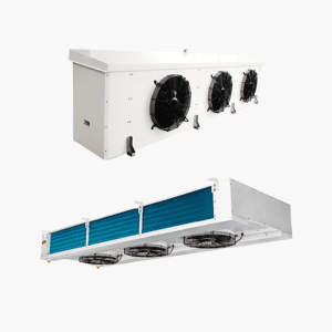
Variable Refrigerant Flow (VRF), also sometimes known as Variable Refrigerant Volume (VRV), is a type of multi-split air conditioning system utilizing a variable refrigerant flow control. This technology allows the system to modulate the amount of refrigerant delivered to multiple individual indoor evaporator units, enabling precise temperature control and increased energy efficiency.
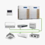
A standard VRF configuration consists of one or more outdoor condensing units connected to numerous indoor units via a network of refrigerant piping. Large-scale VRF systems can involve multiple interconnected outdoor units serving a substantial number of indoor units.
VRF systems are often positioned as a solution offering capabilities between large central chiller plants and smaller individual split AC units, providing design flexibility and favorable energy performance characteristics.
Historical Note: The first VRF/VRV system was developed by Daikin Industries, Ltd. in 1982. The technology is now widely adopted globally across various applications due to its adaptability.
VRF vs. VRV Terminology
The terms VRV (Variable Refrigerant Volume) and VRF (Variable Refrigerant Flow) refer to the same fundamental air conditioning technology. VRV is a registered trademark of Daikin Industries, Ltd. Other manufacturers use the term VRF to describe their equivalent systems based on variable refrigerant flow principles.
Working Principle
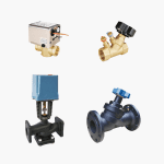
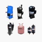
VRF systems operate based on the standard direct expansion (DX) refrigeration cycle, similar to conventional air conditioners. Key components include compressors, fans, heat exchangers (coils), expansion valves, and control systems. Common refrigerants like R-410A are typically used.
The defining characteristic of VRF is its ability to regulate the refrigerant flow to each indoor unit using electronic expansion valves and sophisticated controls, responding precisely to the cooling or heating demands of individual zones.
There are two primary classifications based on the heat rejection method:
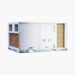
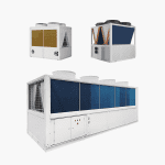
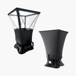
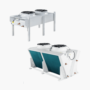
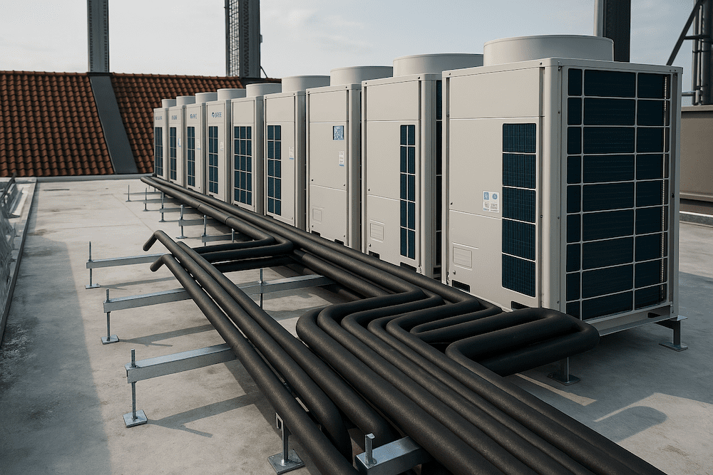
Air-Cooled VRF Systems
Air-cooled VRF outdoor units dissipate heat absorbed from the conditioned space directly into the ambient air. They utilize condenser coils and fans, much like typical residential air conditioners, to transfer heat to the surrounding environment. These units require installation in locations with adequate airflow, such as rooftops or open ground-level areas, and are designed to be weatherproof.
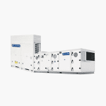
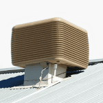
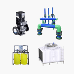
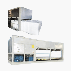
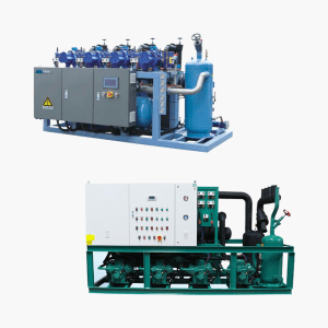
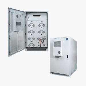
Water-Cooled VRF Systems
Water-cooled VRF units transfer heat from the refrigerant to a circulating water loop. This heated water is then typically pumped to a cooling tower or other heat dissipation equipment where the heat is ultimately rejected, often through evaporation. Water-cooled outdoor units can often be more compact and may offer more flexibility in placement, sometimes being installed within mechanical rooms or service areas.
Key System Characteristics
Operates on the refrigeration cycle principle.
Uses common refrigerants (e.g., R-410A).
Consists of standard AC components (compressor, fan, coil, controls).
Features extensive refrigerant piping networks (total lengths can exceed 1,000 meters).
Utilizes inverter technology for variable compressor speed.
Typically has a higher initial cost compared to standard split systems.
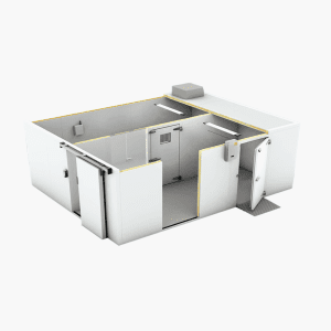
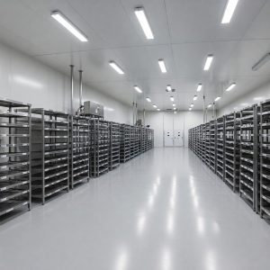
Commonly applied in large residences and commercial buildings.
VRF System Components
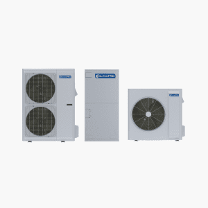
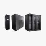
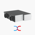
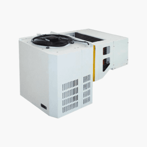
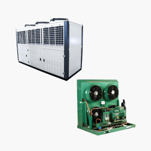
Outdoor Unit
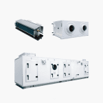
The outdoor unit houses the compressor(s), condenser coil (air or water-cooled heat exchanger), fans (in air-cooled models), and primary control logic.
Capacity: A single air-cooled outdoor unit module can potentially connect to numerous indoor units (e.g., up to 64, depending on manufacturer and model). Multiple modules can be combined for larger capacities.
Placement: Air-cooled units are typically weatherproof and installed outdoors. Significant vertical separation between outdoor and indoor units is often possible (e.g., 20 floors difference). Water-cooled units offer more indoor placement options.
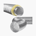
Refrigerant Piping System
The refrigerant piping network in VRF systems differs significantly from standard split systems due to operating pressures, system scale, and control requirements.
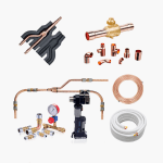
Copper Y-Manifolds (Branch Joints): VRF systems use specialized Y-shaped copper fittings (branch joints or manifolds) to distribute refrigerant from the main pipes to individual indoor units or further branches. These fittings are specific to VRF systems and must match the required pipe diameters. Proper selection and installation (brazing) are critical for system integrity and performance. Incorrect sizing can impede flow, while improper brazing can lead to leaks or joint failure under pressure. Skilled installation is essential.
Copper Pipe and Insulation Specifications: Due to higher operating pressures, VRF systems generally require copper piping with a greater wall thickness than typical split systems. Insulation requirements may also differ; for example, thicker insulation (e.g., 1") might be specified for suction lines compared to the standard 1/2" often used in smaller split systems.
Refrigerant Charge Considerations: VRF systems contain a large volume of refrigerant due to the extensive piping network.
Leak Impact: Refrigerant leaks are particularly problematic, leading to significant refrigerant loss, high replacement costs, and difficulty in locating the leak source within the complex network. Installation quality is paramount to prevent leaks.
Charge Calculation: Manufacturers provide methods or software to calculate the required refrigerant charge based on pipe lengths and system components. Accurate input data is necessary for an accurate calculation.
Charging Practices: While calculated charge is often recommended by manufacturers, field technicians may also rely on pressure readings (e.g., target suction/discharge pressures). Ambient temperature affects pressure readings, leading to debate between calculated mass/volume vs. pressure-based charging. A combination of calculation for estimation and pressure verification during commissioning (ideally during moderate ambient temperatures) is a practical approach. Excess R-410A (a blend) cannot be simply topped off if a leak occurs; a full recovery and recharge may be necessary.
Pressure Testing: A critical installation step is pressure testing the entire refrigerant piping network before charging with refrigerant.
Procedure: The system is typically pressurized with dry nitrogen to high pressures (e.g., potentially 300 psi on the low side, 500 psi on the high side, check manufacturer specifications) and held for a set period (e.g., 24 hours) to ensure there is no pressure drop, indicating a leak-free system.
Safety: The pressures involved are significant (considerably higher than a truck tire). Extreme caution must be exercised during testing. The pressurized lines must be protected from damage, as a rupture could cause injury from expelled gas or metal fragments.
Advantages of VRF Systems
Flexible Design: Allows connection of various types and capacities of indoor units to modular outdoor units, enabling customized solutions for different zones and building requirements. Long piping lengths permit flexible outdoor unit placement.
High Reliability: Often feature multiple compressors within or across outdoor unit modules. If one compressor fails, the system can typically continue operating at reduced capacity using the remaining compressors, minimizing downtime. Modular outdoor units can provide inherent redundancy. (Note: Operation at reduced capacity still necessitates prompt repair).
Space Saving and Aesthetics: Compared to installing an equivalent capacity using individual split systems, VRF requires significantly less outdoor unit footprint. Placing outdoor units on roofs preserves building facade aesthetics. Water-cooled options offer even greater placement discretion.
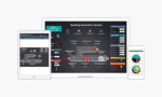
Centralized Monitoring and Control: Typically include sophisticated controls allowing monitoring and management of all indoor units from a central controller or Building Management System (BMS) via standard protocols (e.g., BACnet, MODBUS). Stand-alone manufacturer-provided central controllers are also common.
Low Noise: Indoor units generally operate quietly. The ability to locate outdoor units far from occupied spaces significantly reduces noise intrusion compared to closely located split system outdoor units.
High Efficiency: Variable refrigerant flow, often combined with variable compressor speed (inverter) and potentially variable fan speeds, allows the system to closely match the building load, minimizing energy consumption, especially under part-load conditions. Advanced systems may also incorporate variable refrigerant temperature control.
Suitable Applications
VRF systems are particularly well-suited for buildings where their advantages align with project needs:
Office Buildings (High-rise, Shop Lot, Boutique): Benefit from zoning, diversity factor application (not all zones peak simultaneously, potentially reducing required capacity), centralized control/billing capabilities, and roof placement options.
Large Houses (Bungalow, Villa, Mansion): Leverage diversity factor for cost-effectiveness, provide distinct zone control, and allow discreet outdoor unit placement for aesthetic considerations.
System Variations
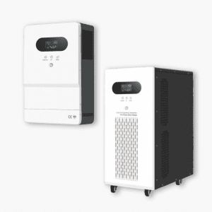
Hot Water Heat Recovery VRF System
These systems (often called 3-pipe systems, see below) can transfer heat rejected during the cooling process to heat water via an additional heat exchanger connected to a hot water storage tank. This improves overall energy efficiency by utilizing waste heat. However, they involve higher initial cost, added complexity (tanks, pumps, piping), and require applications with simultaneous cooling demand and hot water usage to be cost-effective. Dedicated heat pump water heaters can be an alternative for efficient water heating.
3-Pipe VRF System
While standard VRF systems (2-pipe) provide either heating or cooling to all connected indoor units at any given time, 3-pipe VRF systems add a third refrigerant pipe. This allows individual indoor units to operate in either heating or cooling mode independently and simultaneously, providing heat recovery capabilities (transferring heat from cooled zones to heated zones).
Considerations
Cost: Initial equipment and installation costs for VRF systems are generally higher than for multiple individual split systems but can be competitive with or lower than central chiller systems, depending on scale and application. Long-term energy savings contribute to the overall lifecycle cost.
VRF vs. Multi-Split System: A multi-split system connects multiple indoor units to a single outdoor unit but typically lacks the sophisticated variable refrigerant flow control of VRF, resulting in lower efficiency and less precise zoning.
Installation Complexity & Quality: The most significant challenge is ensuring high-quality installation. Improper piping, brazing, or charging can lead to refrigerant leaks, which are difficult and costly to locate and repair in the extensive network, potentially requiring large amounts of refrigerant replacement and significant downtime. Specialized knowledge and skills are essential for installers.
This information provides a general overview of VRF system technology. Specific system capabilities, installation requirements, and performance characteristics vary by manufacturer and model.
For expert advice, system design, high-quality VRF equipment, and professional installation services tailored to your specific needs, please contact ClimaPro.
Climapro Co., Ltd.
Email: [email protected]
We specialize in providing advanced climate control solutions, including state-of-the-art VRF systems.